You are using an out of date browser. It may not display this or other websites correctly.
You should upgrade or use an alternative browser.
You should upgrade or use an alternative browser.
Horsepower for Weight.
- Thread starter Oryx
- Start date
Oryx
Active Member
Sounds great, I’d like to see a sketch of that redesigned air box when you get the time. Good luck with the O390, look forward to your reports.Oryx; I don't think inlet area is the issue. I've not done any numbers for the Husky but I have for other aircraft and the requisite inlet area is surprisingly smaller than you may think.
I'm eager to see if Dogday gets some CFD data and what it will show. From my experience the issue lies in little to no volume of undisturbed air in the plenum the carb draws from. In my designs I maximized this volume and did away with the carb heat flapper that effectively forms a ramp into the carb throat. I instead worked a carb heat inlet at the rear of the newly formed and increased plenum. It would be a fun thing to build.
But I'm still figuring out how to get a fuel injected 390 in my Husky.
Does anyone have a Parts Manual for the 200hp in .pdf they would be willing to send me? I find it way easier to work from paper than trying to switch screens constantly comparing the 180 vrs 200.
Additionally, can someone with a 200 give me the manufacturers Part Numbers for the 2 oil coolers (they're different) and fuel pump?
Thanks a ton
Additionally, can someone with a 200 give me the manufacturers Part Numbers for the 2 oil coolers (they're different) and fuel pump?
Thanks a ton
Oryx
Active Member
Dog
Checking in to see if you’ve had a chance to do any work on the air box? At least 3 people have mentioned plans to build or modify one and I’d like to keep that mod a priority. Keep us posted.
Dogday,In 2017 I made a crude CFD model of Husky's air box (see attached sketch) to see if there was a simple fix such as installing turning vanes to resolve the uneven flow distribution to my carburetor. I could only find a slight improvement in flow distribution with the installation of turning vanes due to the space constraints within the air box. The problematic flow can be resolved, but it will take more than turning vanes in the existing box.
I will be ending my day job in a few months and with my new semiretired lifestyle beginning, I will have more time to pursue my curiosities.
Checking in to see if you’ve had a chance to do any work on the air box? At least 3 people have mentioned plans to build or modify one and I’d like to keep that mod a priority. Keep us posted.
Audette
New Member
I have a lycoming O-360 in my rv-7a - I had the engine Ported, polished, high flow exhaust, dual P-mags and a sensenich carbon prop installed. The engine dyno'd at 213hp - There were probably some other things I could have done to increase the HP, but I didn't want to ruin the life of the engine.
My effort was looking at the uneven air and fuel flow that comes with the stock 180 hp air box. The air box problem was the lack of symmetry in air flow approaching the carb along with the carb's throttle plate interaction. I tried to design a fix that would be limited to the inside of the stock air box such that the average A&P/IA could not easily spot the modification during an annual inspection.Dog
Dogday,
Checking in to see if you’ve had a chance to do any work on the air box? At least 3 people have mentioned plans to build or modify one and I’d like to keep that mod a priority. Keep us posted.
Based on a computational fluid dynamics study, I could only come up with a slight design improvement working within the stock air box using turning and straightening vanes. Things would be much easier if the Husky was not a certified aircraft where a non STC induction system could be installed.
Snowbirdxx
Well-Known Member
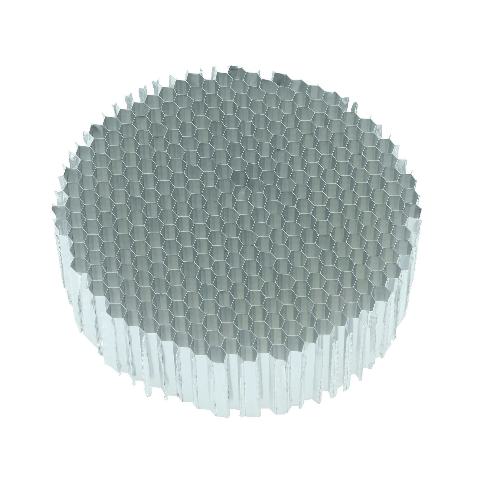
I wonder if a honeycomb straightener between the carb and the oilpan would help. but sticking one of that Honeycomb stainless steel material in the unprotected intake, is not very funny and considering the benefit/ risk...although designed for this purpose in cars
Your opinion please
 www.turbozentrum.de
Your opinion please
MAF Luftmassenmesser Luftberuhiger Wabeneinsatz / Honeycomb 76mm (3")
Verbessert die MAF / Luftmassenmesser Lesewerte
Last edited:
Thomas,
I don't believe that a tightly packed flow straightener after the carb would be of much help. I always thought that the majority of the problem was the 90 bend in the air box feeding directly into the carb. If there was a plenum or two opposing inlets feeding the carb, designing a solution becomes easier.
One question that stands out for me is exactly why when leaning the carb, adding a little carb heat, makes my EGTs even out. I think that it is a combination of better atomization along with the opposing air flow directions that evens out the EGTs; however, I don't know which is the major contributor for what I see. BTW I think that running partial carb heat is a bad idea due to induction pulses vibrating the diverter plate causing its bearings to prematurely wear.
I should have time this summer to make a simple experiment to see if the majority of the correction to EGT variation is carb heat or changing the uneven air flow. On a warm, dry day, with the carb heat hose removed from the air box and replaced with the cold air that normally feeds the muffler heat exchanger, I can see if feeding the carb from the front and back at its inlet cleans up the EGT variation. If it does, then the problem is clearly upstream of the carb. If the problem proves to be upstream of the carb, then a new design air box should be a easy fix to even up the EGTs resulting in better fuel economy and performance provided it is designed correctly. The problem here is to be legal, a new airbox design requires a STC and I doubt that there are enough Huskys around to recover the design and testing costs.
belloypilot
Active Member
One question that stands out for me is exactly why when leaning the carb, adding a little carb heat, makes my EGTs even out. I think that it is a combination of better atomization along with the opposing air flow directions that evens out the EGTs; however, I don't know which is the major contributor for what I see. BTW I think that running partial carb heat is a bad idea due to induction pulses vibrating the diverter plate causing its bearings to prematurely wear.
The consensus of the Advance Pilot Seminar folks in Ada was better atomization accounted for the improved ability to run carbureted engines LOP. Their theory was larger atomized fuel particles tended to separate more through bends in the induction system downstream of the carburetor giving unequal fuel charge delivery. Their theory was raising the temperature a bit tended to give smaller particle sizes and/or more complete vaporization and thereby reduced the problem. They also pointed out the closer you can get to wide open throttle the less problematic this is as well, as the carburetor venturi can act as a more effective straightening vane. They did, however, caution that running partial carb heat on a regular basis may not be a great idea for a number of reasons - their point was to help us understand what was likely going on.
I don't think they had the ability to validate this through hard data, but their empirical experience seemed to align with the theory, as has mine with an albeit much smaller subset of airplanes I've experimented with.
I'll certainly be interested to hear more about the results of your testing. Thanks for the work you're doing to figure this out.
Mike
Mike,The consensus of the Advance Pilot Seminar folks in Ada was better atomization accounted for the improved ability to run carbureted engines LOP. Their theory was larger atomized fuel particles tended to separate more through bends in the induction system downstream of the carburetor giving unequal fuel charge delivery. Their theory was raising the temperature a bit tended to give smaller particle sizes and/or more complete vaporization and thereby reduced the problem. They also pointed out the closer you can get to wide open throttle the less problematic this is as well, as the carburetor venturi can act as a more effective straightening vane. They did, however, caution that running partial carb heat on a regular basis may not be a great idea for a number of reasons - their point was to help us understand what was likely going on.
I don't think they had the ability to validate this through hard data, but their empirical experience seemed to align with the theory, as has mine with an albeit much smaller subset of airplanes I've experimented with.
I'll certainly be interested to hear more about the results of your testing. Thanks for the work you're doing to figure this out.
Mike
Thanks for the info.
The way I look at the issue is that there is a lack of flow symmetry between the front half and back half of the carb's venturi caused by the 90 deg bend at the base of the carb's inlet. This makes for a slight difference in velocity and pressure between the back half of the venturi and front half with higher velocity and lower pressure on the back half. This bias causes a slight difference in droplet size movement depending on whether the air / droplets are on the back or front side of the carb's venturi. Add in carb heat and yes, the fuel is atomized better which results in a more homogeneous flow that is less prone to velocity/pressure forces segregating droplets.
If the air flow was symmetrical through the carb, then droplets would uniformly split between the front and rear cylinders resulting in a more uniform flow to all of the cylinders. Because our O-360 are 4 cylinder, it should not be too difficult to get left to right and front to back symmetry in flow with a non certified induction system. So I am not disagreeing with Advance Pilot Seminar folks; however, they are not looking at the root cause of an opposed 4 cylinder engine's induction system's symmetry. An opposed 6 has significant induction symmetry issues on the downstream side of the carb as well that are more complicated to resolve than our 4 bangers.
Snowbirdxx
Well-Known Member
What do you guy think of this rudimental method to try out what improvements could be done.
Record EGTs at different power settings
Remove Airbox
Install one made for that purpose that curves nice up into the carb, no carb heat, no filter
Fly again on a dry day and record EGTs#
Compare EGTs
Record EGTs at different power settings
Remove Airbox
Install one made for that purpose that curves nice up into the carb, no carb heat, no filter
Fly again on a dry day and record EGTs#
Compare EGTs
Thomas, what you said would work.
My thoughts: No matter how a bend is made, it would take a flow straightener along with a straight section before the carb, or a large plenum to get a uniform cross section of air entering the carb. There is not enough room under the cowl for this to happen. Then there is the throttle plate in the carb that adds in additional issues. At best, we could only make an improvement towards uniform flow entering the carb. Before I would go to the effort to build/design a new air box for experimentation, I would want to know if the results were worth the effort. Wouldn't it be great fun to have a dyno to do this work?
By disabling the carb heat as I described above and having outside air from the nose bowl feed the air box's carb heat port, then the carb heat control (the red knob) could be used to tune the inlet air for the carb. If there was a setting that had a healthy improvement for EGT symmetry that worked from a slow cruise setting to WOT, then it could be determined if making a new air box design was worth the effort. This air box test with carb heat replaced with outside air would create flow from opposing directions that would tend to cancel out some of the problem as well as adding a bit of plenum before the carb.
Great discussion. In my experience every application we worked with had similar restraints on what could be done to feed the intake (carb or FI). In all cases we worked hard to create the largest mass of relatively undisturbed air or a plenum. None of this could be tested as the dyno was stationary and the issues arose when in motion. What seemed most successful was an intake scoop necked down longitudinally and expanded into a plenum feeding all intakes. Here's the best pic I could find easily:Thomas, what you said would work.
My thoughts: No matter how a bend is made, it would take a flow straightener along with a straight section before the carb, or a large plenum to get a uniform cross section of air entering the carb. There is not enough room under the cowl for this to happen. Then there is the throttle plate in the carb that adds in additional issues. At best, we could only make an improvement towards uniform flow entering the carb. Before I would go to the effort to build/design a new air box for experimentation, I would want to know if the results were worth the effort. Wouldn't it be great fun to have a dyno to do this work?
By disabling the carb heat as I described above and having outside air from the nose bowl feed the air box's carb heat port, then the carb heat control (the red knob) could be used to tune the inlet air for the carb. If there was a setting that had a healthy improvement for EGT symmetry that worked from a slow cruise setting to WOT, then it could be determined if making a new air box design was worth the effort. This air box test with carb heat replaced with outside air would create flow from opposing directions that would tend to cancel out some of the problem as well as adding a bit of plenum before the carb.
.png")
I personally am less interested in "legal" and more interested in solving the technical issue. I started building a prototype airbox but got sidetracked. I'll be getting back on it soon.
Side note, you are right on about 4 cylinder / 6 cylinder / opposed intake distribution. The above car uses a small block Chevy V8 and when porting the heads we asymmetrically shaped ports taking port location and firing order into account.
Oryx
Active Member
Another possible experiment could be introducing additional filtered air from another location and ducting it into a new port in the side of the air box. The duct would probably be smaller than the main intake but if the theory is correct it seems it would still help. Maybe two smaller ones.Thomas, what you said would work.
My thoughts: No matter how a bend is made, it would take a flow straightener along with a straight section before the carb, or a large plenum to get a uniform cross section of air entering the carb. There is not enough room under the cowl for this to happen. Then there is the throttle plate in the carb that adds in additional issues. At best, we could only make an improvement towards uniform flow entering the carb. Before I would go to the effort to build/design a new air box for experimentation, I would want to know if the results were worth the effort. Wouldn't it be great fun to have a dyno to do this work?
By disabling the carb heat as I described above and having outside air from the nose bowl feed the air box's carb heat port, then the carb heat control (the red knob) could be used to tune the inlet air for the carb. If there was a setting that had a healthy improvement for EGT symmetry that worked from a slow cruise setting to WOT, then it could be determined if making a new air box design was worth the effort. This air box test with carb heat replaced with outside air would create flow from opposing directions that would tend to cancel out some of the problem as well as adding a bit of plenum before the carb.
I may easily be wrong .... but. I don't think adding more air entry to the existing airbox would do much. As I see it there are 2 primary difficulties with the existing design: 1) the carb intake has a nice bell opening - but the airbox ignores this and places a tube against this bell defeating the bell. 2) the airbox is rather flat, not much height, and the warm air flopper plate presents a ramp in close proximity to the tube running to the carb.Another possible experiment could be introducing additional filtered air from another location and ducting it into a new port in the side of the air box. The duct would probably be smaller than the main intake but if the theory is correct it seems it would still help. Maybe two smaller ones.
So the transition from airbox to barb is compromised; the overall volume of the airbox is compromised; and the floor of the airbox induces a bunch of turbulence feeding the carb.
I admit I'm more of an experimenter than an analyzer. Nothing bad about CFD and the like; it's super neat. But I don't have a big computer and fancy software; but I do have a shop full of tools
") . What I intend to try is a whole new airbox: the top plane of this airbox bolts directly to the carb. This way the bell-mouth of the carb is utilized and the overall volume of the airbox is nearly doubled. Second is to toss the warm air flopper and come up with a different scheme for warm air that does not negatively impact airflow. This leaves the bottom plane of the airbox flat and normal to the carb. And it all fits within the existing cowl. In my mind it's worth a try.
. What I intend to try is a whole new airbox: the top plane of this airbox bolts directly to the carb. This way the bell-mouth of the carb is utilized and the overall volume of the airbox is nearly doubled. Second is to toss the warm air flopper and come up with a different scheme for warm air that does not negatively impact airflow. This leaves the bottom plane of the airbox flat and normal to the carb. And it all fits within the existing cowl. In my mind it's worth a try.A couple thoughts on the butterfly affecting airflow. I see this as high-fruit; this method has been around a long time and been successful and attempts that I know of to get around it like slide valves didn't show any improvement. So while I would agree that theoretically it is not ideal; practically it works and isn't where I'd spend effort on. Second is that the carb, or at least the Avstar that my engine came with, has an enrichening circuit at WOT that is eliminated right off WOT. So the carb was designed to cruise off WOT. Not saying this is how I would like it, just that it's there and impacts the butterfly position.
oops, I meant to say the black knob that controls the carb heat diverter plate.
As far as a experiment having outside air replace the hot air on the back of the air box, this would introduce air from both the front and back of the air box and could be tuned with the carb heat diverter plate. If there was one setting where the EGTs tracked better from cruise to WOT, then that would tell me that it is worth the effort to design and build a new air box and that there is a significant problem with the existing air box that can be fixed. Having converging flow from two directions might cancel out some of the uneven flow; however, something like a simple tee is a bad idea for converging the flow from two directions because of the added pressure drop. This air box test would only confirm that most of the problem with uneven EGTs on the O-360 are due the the crappy air inlet design.
As far as a experiment having outside air replace the hot air on the back of the air box, this would introduce air from both the front and back of the air box and could be tuned with the carb heat diverter plate. If there was one setting where the EGTs tracked better from cruise to WOT, then that would tell me that it is worth the effort to design and build a new air box and that there is a significant problem with the existing air box that can be fixed. Having converging flow from two directions might cancel out some of the uneven flow; however, something like a simple tee is a bad idea for converging the flow from two directions because of the added pressure drop. This air box test would only confirm that most of the problem with uneven EGTs on the O-360 are due the the crappy air inlet design.
Snowbirdxx
Well-Known Member
Please keep in mind that if you open the butterfly valve ( pull partial carb heat ) that the filtered incoming air is escaping through the large hole on the bottom of the carbbox.
Last edited:
Your right Thomas, I failed to consider that. Looks like I would need to cover the bottom of the box for the experment.
Clifford's approach may be the best way forward. I just wanted an easy way to see some indication that the effort to design and build a better air box would be worth the effort. Furthermore I really don't know how much of the uneven fuel distribution comes from flow issues related to the carb's throttle plate.
Clifford's approach may be the best way forward. I just wanted an easy way to see some indication that the effort to design and build a better air box would be worth the effort. Furthermore I really don't know how much of the uneven fuel distribution comes from flow issues related to the carb's throttle plate.